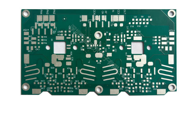
The printed circuit board plays a pivotal role in modern electronics, serving as the backbone of countless devices. Whether you’re designing for consumer gadgets or industrial machinery, the right PCB board ensures reliability and efficiency. Mistakes like placing components too close to the edge or using unnecessary layers can compromise your project’s success. Proper planning helps you avoid these pitfalls and ensures your PCB meets performance demands. By understanding your application’s requirements, you can create a robust design that supports both functionality and durability.
Key Takeaways
- Know what your project needs. Decide if your PCB is for testing or making many copies, and plan your design.
- Pick the right materials for your project. For example, use FR4 for regular projects or aluminum for handling heat in powerful devices.
- Think about the environment early. Check for heat and moisture to make sure your PCB works well where it will be used.
- Balance cost and quality wisely. Don’t make simple projects too fancy, but use good materials for important ones.
- Work with your manufacturer. Talking early helps check designs and ensures your PCB can be made properly.
Define Your Project Requirements
Understand the Purpose of Your PCB
Is it for prototyping or mass production?
The purpose of your printed circuit board determines its design and manufacturing approach. If your project involves prototyping, you’ll need flexibility for design changes and quick iterations. Prototyping allows you to test and validate your design before committing to mass production. On the other hand, mass production focuses on cost efficiency and standardized processes to produce large quantities. For example:
| Feature | PCB Prototyping | PCB Mass Production |
|---|---|---|
| Purpose | Test and validate designs before mass production | Manufacture large quantities for commercial purposes |
| Flexibility | High; allows for design changes and iterations | Low; relies on standardized processes |
| Cost | Higher unit cost, economical for testing | Lower unit cost, cost efficiencies through volume |
Understanding this distinction helps you align your PCB board design with your project requirements.
What is the intended application (e.g., consumer electronics, industrial use)?
The application of your PCB influences its design and material selection. Consumer electronics often prioritize compactness and cost-effectiveness, while industrial applications demand durability and resistance to harsh conditions. For instance, a PCB for a wearable device must be lightweight and slim, whereas one for industrial machinery may require robust materials to withstand vibrations and mechanical stress.
Determine Electrical and Mechanical Needs
Voltage, current, and signal requirements.
Electrical performance is a critical factor in PCB design. You must consider voltage levels, current-carrying capacity, and signal integrity. High-frequency applications require materials with low dielectric loss to ensure efficient signal transmission. Impedance control is also essential for maintaining signal quality, especially in complex designs.
Size, shape, and layer count considerations.
Mechanical properties like size, shape, and layer count directly impact your PCB’s functionality. A slim profile is ideal for compact devices, but thicker circuits may be necessary for higher current demands. Thinner copper layers enhance flexibility, making them suitable for applications requiring mechanical agility. Balancing these needs ensures your PCB meets both electrical and mechanical requirements.
Consider Environmental Factors
Will the PCB be exposed to extreme temperatures or moisture?
Environmental conditions significantly affect PCB performance. High-temperature applications require materials with excellent thermal properties to prevent damage from heat generated by components. Moisture resistance is equally important for PCBs exposed to humidity or water. For example, outdoor devices must withstand rain and temperature fluctuations.
Does it need to meet specific industry standards (e.g., IPC, RoHS)?
Compliance with industry standards ensures your PCB meets safety and performance benchmarks. IPC standards define quality and reliability, while RoHS compliance restricts hazardous substances. These certifications are especially crucial for PCBs used in regulated industries like healthcare or automotive.
Tip: Always evaluate environmental factors early in the design process to avoid costly redesigns later.
Material Selection and Quality for PCB Boards
Choose the Right Substrate Material
FR4 for general use, aluminum for heat dissipation, etc.
Selecting the right substrate material is crucial for ensuring the quality and performance of your PCB. FR4, a widely used material, offers several advantages:
- Cost-effectiveness: FR4 is affordable and readily available, making it ideal for mass production.
- Versatility: It supports both through-hole and surface-mount components, accommodating diverse designs.
- Ease of fabrication: FR4 works seamlessly with standard manufacturing techniques like drilling and soldering.
However, FR4 has limitations. Its moderate thermal conductivity can lead to heat dissipation challenges in high-power applications. It may also struggle under extreme mechanical stress or high-frequency conditions. For projects requiring better heat management, aluminum substrates provide superior thermal performance, making them suitable for LED lighting or power electronics.
High-frequency materials for RF applications.
For high-frequency applications, such as RF circuits or microwave devices, you need materials with low dielectric loss. These materials maintain signal integrity and reduce losses, ensuring reliable performance. Options like PTFE or ceramic-filled substrates excel in these scenarios, though they come at a higher cost.
Evaluate Copper Thickness
Standard vs. heavy copper for current-carrying capacity.
Copper thickness directly impacts the electrical and thermal performance of your PCB. Standard copper thickness works well for most applications, ensuring good conductivity and cost efficiency. However, heavy copper is essential for high-current designs or environments requiring enhanced heat dissipation. While thicker copper reduces resistance and improves signal quality, it increases manufacturing costs and complexity. Balancing these factors ensures your PCB meets both performance and budgetary needs.
Assess Surface Finish Options
HASL, ENIG, or OSP based on durability and cost.
The surface finish of your PCB affects solderability, durability, and cost. Common options include:
| Surface Finish | Cost Comparison | Durability and Performance Characteristics |
|---|---|---|
| Organic Solderability Preservative (OSP) | Least expensive | Good solderability for a limited time; less durable; suitable for short-term applications. |
| HASL (Hot Air Solder Leveling) | Relatively low | Good balance between cost and performance; uneven surface can challenge fine-pitch components. |
| Electroless Nickel Immersion Gold (ENIG) | More expensive | Flat surface ideal for fine-pitch components; excellent corrosion resistance; suitable for high-reliability applications. |
For high-reliability applications, ENIG offers superior quality and durability. OSP, while cost-effective, suits short-term or low-budget projects. Choosing the right finish ensures your PCB meets the demands of its intended application.
Tip: Always evaluate the trade-offs between cost and performance when selecting materials and finishes to ensure the highest quality for your project.
Budget Constraints in Choosing a PCB Board
Balance Cost and Quality
Avoid over-engineering for simple projects.
Over-engineering a PCB can inflate costs unnecessarily, especially for simple projects. For instance, adding extra layers or using high-performance materials like ceramic when FR-4 suffices can strain your budget. Focus on the essential features your project requires. Simplify the design and avoid unnecessary complexities to keep pricing manageable.
Invest in higher-quality materials for critical applications.
Critical applications demand higher-quality materials to ensure durability and reliability. For example, investing in finishes like ENIG or using aluminum substrates for heat dissipation can enhance performance and longevity. While the upfront cost may be higher, the long-term benefits, such as reduced maintenance and improved production yields, justify the investment.
Tip: Evaluate the trade-offs between cost and quality to align with your project’s goals.
Factor in Manufacturing Costs
Single-layer vs. multi-layer PCBs.
The number of layers in your PCB significantly impacts manufacturing costs. Single-layer PCBs are cost-effective and simpler to produce, making them ideal for basic designs. Multi-layer PCBs, while more expensive, support complex circuits and save space in compact devices. Consider the following comparison:
| Aspect | Multi-Layer PCBs | Single-Layer PCBs |
|---|---|---|
| Production Costs | Higher due to complex fabrication | Lower due to simpler processes |
| Design Complexity | Requires specialized knowledge | Less complex |
| Troubleshooting Difficulty | Increased due to multiple layers | Easier due to single layer |
Additional costs for advanced features like blind vias.
Advanced features, such as blind or buried vias, enhance functionality but increase pricing. These features require specialized manufacturing processes, which can extend turnaround times. Use them only when necessary to balance cost and performance.
Plan for Prototyping and Scaling
Use cost-effective options for prototypes.
Prototyping allows you to test your design before mass production. Opt for cost-effective materials like FR-4 and simpler designs to minimize expenses during this phase. For example, using single-layer PCBs for prototypes can reduce costs while still providing valuable insights.
Optimize design for mass production.
Design for manufacturability (DFM) ensures your PCB is optimized for mass production. Simplify layouts, minimize layers, and use standard board sizes to reduce material waste and production complexity. The benefits of DFM include:
| Benefit | Description |
|---|---|
| Reduced Production Costs | Simplified designs lower assembly costs and material waste. |
| Shortened Time-to-Market | Streamlined designs improve turnaround times. |
| Improved Product Quality | Fewer flaws result in more reliable products. |
| Increased Production Efficiency | Enhanced speed and consistency in manufacturing processes. |
Note: Collaborate with your manufacturer early to validate designs and avoid costly rework.
Ensuring Compatibility with Design and Assembly
Match PCB Design to Assembly Process
Ensure compatibility with SMT or through-hole components.
You must align your PCB design with the assembly process to ensure smooth production. Surface Mount Technology (SMT) and through-hole components require different design approaches. SMT components are compact and suitable for high-density designs, while through-hole components offer better mechanical stability. Choose materials that support the intended assembly method. For advanced techniques like via-in-pad or HDI, specific materials enhance drillability and etching precision.
Consider assembly tolerances and clearances.
Assembly tolerances and clearances play a critical role in ensuring compatibility. Maintain proper spacing between components to prevent soldering issues or shorts. Include solder mask clearances to avoid pad overlaps. Ensure silkscreen text is legible for easy identification during assembly. These steps reduce errors and improve production efficiency.
Verify Design Rules
Follow manufacturer-specific design guidelines.
Every manufacturer has unique design rules. Adhering to these guidelines ensures your PCB meets their production capabilities. For example, improper annular rings or insufficient copper trace widths can lead to manufacturing defects. Always confirm that your design complies with the manufacturer’s specifications to avoid costly revisions.
Use design software with built-in DRC (Design Rule Check).
Modern PCB design software includes features like Design Rule Check (DRC) to identify potential violations. Use these tools to detect issues such as exposed copper or improper trace spacing. Advanced software also offers auto-routing and multilayer board design, streamlining the engineering process and improving compatibility with manufacturing.
Plan for Component Placement
Optimize layout for signal integrity and thermal management.
Proper component placement is essential for signal integrity and thermal performance. Group components by function, such as power regulation or high-speed signals, to simplify routing and reduce noise. Position high-speed components close to each other to minimize trace lengths. Maintain at least 10 mil of courtyard clearance around components to ensure effective heat dissipation.
Avoid overcrowding components.
Overcrowding components can lead to assembly challenges and performance issues. Organize components based on their functionality and maintain optimal spacing. Start placement with connectors, followed by power circuits, precision circuits, and critical circuits. This order helps manage power levels and reduces noise susceptibility. Include test points for efficient troubleshooting and ensure consistent orientation for easier inspection.
Tip: Clear component outlines and reference centroids improve alignment during assembly, reducing the risk of errors.
Choosing the Right PCB Manufacturer
Selecting the right manufacturer is a critical step in ensuring your PCB board meets the demands of your project. A reliable partner can help you achieve high-quality results, streamline production, and avoid costly delays. Here are key factors to consider when choosing a PCB manufacturer.
Research Manufacturer Expertise and Reputation
Look for experience in your industry or application.
A manufacturer’s expertise directly impacts the success of your project. Look for companies with experience in your specific industry or application. For example, a manufacturer specializing in automotive PCBs will better understand the durability and performance requirements for that sector. Consider the following factors when evaluating expertise and reputation:
- Years of experience in PCB manufacturing.
- Proven track record in your industry.
- Positive reputation and reviews from previous clients.
- Strong quality control processes.
Check for certifications and quality standards.
Certifications demonstrate a manufacturer’s commitment to quality and reliability. Look for certifications such as ISO for quality management systems, UL for safety compliance, and IPC for high manufacturing standards. If your project involves military applications, ensure the manufacturer meets military specifications. These certifications guarantee that the manufacturer adheres to strict quality standards.
Evaluate Production Capabilities
Minimum order quantities and lead times.
Understanding a manufacturer’s production capabilities helps you plan effectively. Some manufacturers impose minimum order quantities, which may not suit small-scale projects. Additionally, lead time varies by manufacturer and order complexity. For example:
| Lead Time Type | Duration | Notes |
|---|---|---|
| Standard Lead Time | 20 working days | Suitable for most rigid PCBs. |
| Quick Turn | Less than 20 working days | Higher costs apply. |
| 1-4 Layers | 1-6 days | Varies by layer count. |
| 6-10 Layers | 2-6 days | Varies by layer count. |
| > 10 Layers | 3-5 days | Varies by layer count. |
Discuss lead time expectations with your manufacturer to avoid delays.
Advanced features like HDI or flexible PCBs.
If your project requires advanced features, such as HDI or flexible PCBs, confirm the manufacturer has the necessary capabilities. Not all manufacturers can handle complex designs, so ensure they have the equipment and expertise to meet your requirements.
Assess Customer Support and Reliability
Availability of design assistance and technical support.
Manufacturers offering design assistance and technical support can significantly enhance your project’s success. They can help you identify design flaws, optimize layouts, and reduce costs. This support saves time and effort while improving time-to-market capabilities. Working with a manufacturer that provides these services ensures your PCB meets both functional and business requirements.
Responsiveness to inquiries and issues.
Reliable customer support is essential for addressing questions or resolving issues quickly. Evaluate how responsive the manufacturer is to inquiries and whether they provide clear communication throughout the process. A manufacturer with strong customer support ensures a smoother production experience and builds trust.
Tip: Always ask questions to assess a manufacturer’s reliability, such as their approach to quality control, lead times, and customer support.
By carefully evaluating these factors, you can choose a PCB manufacturer that aligns with your project’s needs and ensures high-quality results.
Testing and Validation for PCB Boards
Testing and inspection are essential steps in ensuring the reliability of your PCB. These processes verify that the board meets design specifications and can withstand real-world conditions. By conducting thorough testing, you can identify potential issues early and improve the overall quality of your project.
Perform Electrical Testing
Continuity and insulation resistance tests.
Electrical testing ensures your PCB performs as intended. Continuity tests check for open circuits and shorts by passing DC current through the board. Insulation resistance tests evaluate the isolation between different nets, which is critical for high-voltage applications. Additional methods like in-circuit testing measure specific voltage and current values at test points, while time domain reflectometry (TDR) assesses impedance to maintain signal integrity. These tests confirm that your board meets electrical performance requirements.
Functional testing for specific applications.
Functional testing powers up the PCB to verify its overall operation. This step ensures the board performs as expected in its intended application. For smaller batches, flying probe testing offers a cost-effective solution by evaluating electrical properties without requiring custom fixtures. These tests help you detect issues like short circuits or faulty components, ensuring the reliability of your design.
Conduct Environmental Testing
Thermal cycling, vibration, and humidity tests.
Environmental testing evaluates how your PCB withstands extreme conditions. Thermal cycling exposes the board to rapid temperature changes, simulating real-world scenarios. Vibration testing ensures mechanical stability, while humidity tests assess the board’s resistance to moisture. These tests confirm that your PCB can handle harsh environments without compromising performance.
Compliance with industry standards.
Adhering to industry standards like IPC ensures your PCB meets quality benchmarks. These standards promote consistency and reliability, reducing manufacturing errors and material waste. Compliance also builds trust with stakeholders and enhances your product’s reputation. Testing and inspection aligned with these standards streamline workflows and minimize costly rework.
Iterate and Improve
Use feedback from testing to refine the design.
Testing results provide valuable insights for improving your PCB. Addressing issues like signal interference or thermal management during this phase enhances the board’s performance. Iterative improvements ensure your design meets both functional and environmental requirements.
Collaborate with the manufacturer for adjustments.
Working closely with your manufacturer allows you to implement design changes efficiently. Manufacturers can offer technical support and suggest optimizations based on testing outcomes. This collaboration ensures your PCB achieves the desired reliability and functionality.
Tip: Incorporate testing and inspection early in the development process to avoid delays and costly redesigns.
Choosing the right PCB board is a cornerstone of any successful project. By carefully evaluating factors like thermal properties, electrical performance, and environmental durability, you can ensure your PCB meets the demands of its application. For industries such as medical and aviation, rigorous testing and validation processes are indispensable. These tests simulate real-world conditions, identifying potential failures and confirming reliability under thermal stress, vibration, and other challenges. This meticulous approach guarantees dependable performance, especially in critical applications. Apply these strategies to streamline your PCB selection process and achieve outstanding results.
FAQ
What role do PCB boards play in medical devices?
PCB boards ensure precision and reliability in medical devices. They support critical functions like monitoring vital signs, powering imaging systems, and enabling portable diagnostic tools. High-quality PCBs meet strict safety standards, ensuring dependable performance in life-saving applications.
Why are PCBs essential in automotive electronics?
PCBs power advanced automotive systems, including engine controls, infotainment, and safety features like airbags. They withstand harsh conditions such as vibrations and temperature fluctuations, ensuring durability. Their compact design supports the growing demand for lightweight, efficient vehicles.
How do PCBs contribute to aerospace technology?
PCBs enable high-performance systems in aerospace, such as navigation, communication, and control modules. They use specialized materials to endure extreme temperatures and radiation. Their reliability ensures mission-critical operations in satellites, aircraft, and space exploration.
Are PCBs important in renewable energy systems?
PCBs optimize renewable energy systems like solar panels and wind turbines. They manage power conversion, storage, and distribution efficiently. Their durability ensures long-term performance in outdoor environments, supporting sustainable energy solutions.
What makes PCBs vital in consumer electronics?
PCBs form the backbone of consumer electronics, from smartphones to gaming consoles. They provide compact, efficient designs that support high-speed processing and connectivity. Their versatility allows manufacturers to create innovative, user-friendly devices.
Tip: Choose PCB materials and designs tailored to your industry to maximize performance and reliability.