Automotive PCBs play a critical role in modern vehicles, ensuring seamless operation of advanced electronic systems. Their manufacturing process demands precision and adherence to strict quality standards. Over the years, the global demand for automotive PCBs has surged, growing from $4.6 billion in 2014 to over $7 billion by 2020. This growth reflects the increasing reliance on electronics in vehicles, where the average value of electronic components has risen from $100 in the 1970s to $2,000 in recent years. To meet these demands, manufacturers employ advanced materials and techniques, ensuring durability and performance under harsh conditions.
Key Takeaways
- Automotive PCBs are important for car electronics to work well.
- Special materials and thick copper help signals and power flow better.
- Makers follow strict rules like ISO 26262 for safety and reliability.
- Good heat control stops overheating, so PCBs work in hot or cold.
- Careful testing ensures automotive PCBs meet high performance needs.
Characteristics of Automotive PCBs
High Reliability and Durability
Automotive PCBs are designed to endure the harshest conditions while maintaining consistent performance. You rely on these PCBs to function flawlessly throughout a vehicle’s lifespan, which typically ranges from 10 to 12 years. During this time, they must withstand extreme temperature fluctuations, from scorching summers to freezing winters. Additionally, they endure constant vibrations, shocks, and exposure to humidity.
- The average lifespan of vehicles has increased from 8-10 years in the 1990s to 10-12 years today, emphasizing the need for durable PCBs.
- Automotive PCBs must operate reliably in environments with temperature variations and mechanical stress.
This level of reliability ensures that critical automotive systems, such as engine control units and safety features, perform without failure, even in the most demanding scenarios.
Use of High-Frequency Substrates
Modern vehicles incorporate advanced communication systems, radar, and sensors, which require high-frequency substrates. These substrates enable the transmission of signals at higher frequencies with minimal loss. You benefit from this technology in applications like adaptive cruise control, collision avoidance systems, and GPS navigation.
High-frequency substrates also improve signal integrity, ensuring that data transmission remains accurate and uninterrupted. This is crucial for the seamless operation of automotive electronics, especially in autonomous and connected vehicles.
Thick Copper Layers for High Current
Automotive PCBs often feature thick copper layers to handle high current demands and dissipate heat effectively. These PCBs are essential for electric power transmission systems in vehicles, especially in electric and hybrid models.
- Thick copper PCBs, with a copper thickness greater than 3 oz (105µm), enhance current-carrying capacity and thermal endurance.
- They replace bulky cable harnesses, allowing high and low current components to integrate on the same board.
- These PCBs manage the heat generated by high-density automotive electronics, ensuring optimal performance.
Fabricating multi-layered PCBs with thick copper is complex, but it provides the durability and efficiency required for high-performance automotive systems.
Heat Resistance and Thermal Management
Automotive PCBs must operate reliably in extreme temperature conditions. You depend on these PCBs to function seamlessly, whether in freezing winters or scorching summers. Effective heat resistance and thermal management are critical to maintaining their performance and longevity.
To meet these demands, manufacturers design PCBs with materials that dissipate heat efficiently. High-temperature laminates, thermal vias, and heat sinks are commonly used to manage heat generated by high-power components. These strategies prevent overheating, which could otherwise lead to component failure or reduced efficiency.
The temperature thresholds for automotive PCBs vary depending on their position within the vehicle. The table below highlights the temperature ranges for different grades of PCBs:
| Grade | PCB Position | Low Temperature | High Temperature |
|---|---|---|---|
| A | Within the Cockpit | -40 °C | 85 °C |
| B | Below the Base Shield | -40 °C | 125 °C |
| C | Motor | -40 °C | 145 °C |
| D | Driving Medium | -40 °C | 155 °C |
| E | Inner Motor | -40 °C | 165 °C |
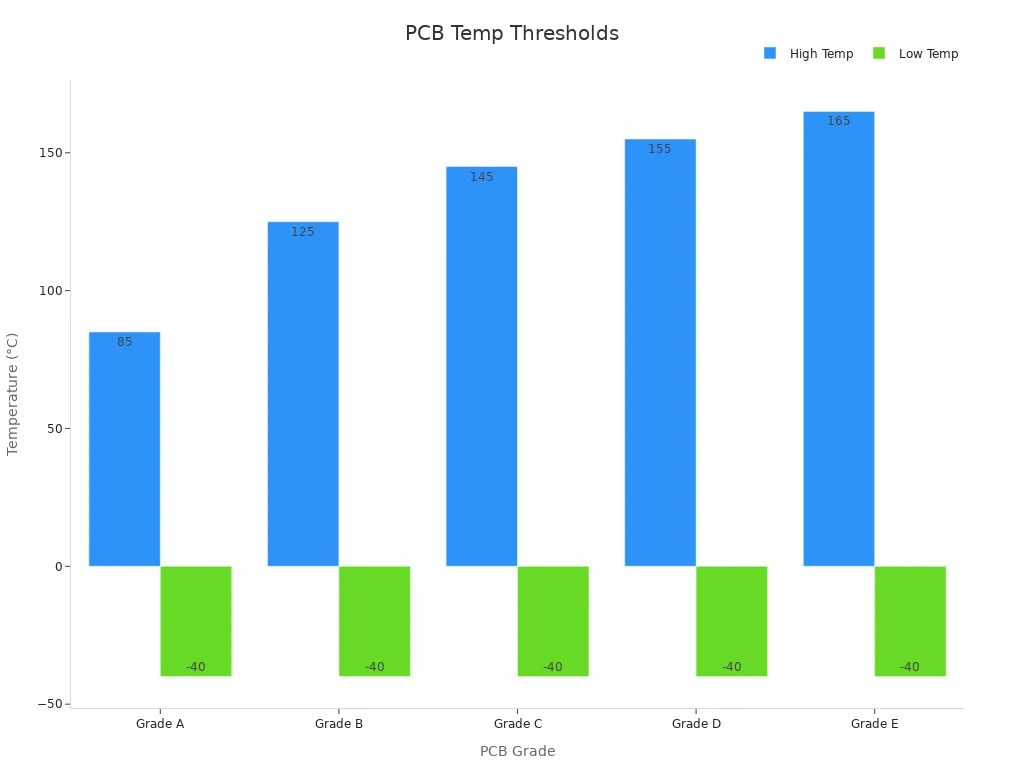
These temperature thresholds demonstrate the robust heat resistance of automotive PCBs. For example, PCBs within the motor can withstand temperatures as high as 165 °C. This ensures that even under heavy loads, your vehicle’s electronics remain operational.
Compliance with Automotive Standards
Automotive PCBs must adhere to stringent industry standards to ensure safety and reliability. These standards validate that the PCBs can withstand harsh environments and perform critical functions without failure.
Two key certifications for automotive PCBs include:
| Standard | Description |
|---|---|
| ISO 26262 | A standard for functional safety of electrical and electronic systems in production automobiles. |
| AEC-Q100 | A qualification standard for integrated circuits used in automotive applications, ensuring reliability under harsh conditions. |
ISO 26262 focuses on functional safety, ensuring that electronic systems in your vehicle operate without causing harm. AEC-Q100, on the other hand, guarantees that integrated circuits can endure the demanding conditions of automotive environments. Together, these certifications provide you with confidence in the reliability and safety of automotive PCBs.
By meeting these standards, manufacturers ensure that automotive PCBs deliver consistent performance, even in the most challenging scenarios. This compliance is essential for critical systems like braking, steering, and engine control, where failure is not an option.
Types of Automotive PCBs
Rigid Automotive PCBs
Rigid automotive PCBs are the backbone of many vehicle electronic systems. These PCBs are made from solid, inflexible materials, making them ideal for applications requiring structural stability. You’ll find rigid PCBs in engine control units, power management systems, and infotainment modules. Their durability ensures consistent performance in environments with high vibrations and mechanical stress.
The demand for rigid PCBs has grown significantly due to advancements in electric vehicles and autonomous driving technologies. Manufacturers value their ability to handle complex circuitry while maintaining reliability.
| Year | Global Requirement of PCBs (USD) |
|---|---|
| 2014 | 4.6 billion |
| 2020 | 7 billion |
This growth highlights the increasing reliance on robust PCBs in modern vehicle manufacturing.
Flexible Automotive PCBs
Flexible PCBs offer unmatched versatility in automotive design. These PCBs are made from materials like polyimide, which provide flexibility and high thermal stability. You’ll see them used in cramped spaces and high-temperature environments, such as under the hood or within advanced driver assistance systems (ADAS).
- The rise of electric vehicles has increased the need for flexible PCB solutions.
- ADAS and other complex vehicle electronics drive the adoption of flexible PCBs.
| Material Type | Characteristics | Applications |
|---|---|---|
| Polyimide | Flexibility, high thermal stability | Ideal for high-temperature environments and cramped spaces in vehicles |
Flexible PCBs reduce the need for connectors, simplifying assembly and improving reliability. Their lightweight design also contributes to better fuel efficiency in traditional vehicles and extended range in electric models.
Rigid-Flex Automotive PCBs
Rigid-flex PCBs combine the best features of rigid and flexible PCBs. These hybrid boards consist of rigid sections connected by flexible layers, offering both structural integrity and adaptability. You’ll find them in applications requiring compact designs and high durability, such as airbag systems and battery management units.
| Performance Aspect | Rigid PCBs | Flexible PCBs | Rigid-Flex PCBs |
|---|---|---|---|
| Flexibility | No | Yes | Some sections |
| Connectivity | No | Requires connectors | Built-in |
| Weight | Heaviest | Lightest | Moderate |
| Durability | Strong but not shock-absorbent | Flexible and shock-absorbent | Suitable for harsh environments |
| Assembly | Complex | Simple | Easier than rigid |
| Environmental Resistance | Vulnerable | More resistant | Highly resistant |
The global rigid-flex PCB market was valued at approximately USD 1.2 billion in 2023 and is projected to reach USD 2.5 billion by 2032, growing at a CAGR of 8.5%. This growth reflects the automotive industry’s increasing reliance on advanced electronics.
LED Automotive PCBs
LED automotive PCBs are essential for modern vehicle lighting systems, offering superior efficiency and durability. These PCBs are commonly made with aluminum substrates, which provide excellent thermal management. You’ll notice their application in headlights, taillights, and interior lighting, where consistent performance is critical.
Key advantages of LED automotive PCBs include:
- Enhanced Thermal Management: Aluminum substrates transfer heat efficiently, with thermal conductivity ranging from 1W/m.K to 8W/m.K. This ensures LEDs operate at optimal temperatures, even during extended use.
- Dimensional Stability: Aluminum resists deformation under high temperatures, maintaining the PCB’s structural integrity.
- Compact Design: Infineon’s automotive LED solutions optimize space on the PCB while managing power dissipation effectively.
These features allow manufacturers to design lighting systems with higher LED densities and longer runtimes. Aluminum’s durability and recyclability also make it an environmentally friendly choice for automotive applications.
LED PCBs have revolutionized vehicle lighting by improving energy efficiency and reducing maintenance needs. Their ability to withstand harsh conditions ensures reliable performance, whether you’re driving in extreme heat or freezing temperatures.
HDI Automotive PCBs
High-Density Interconnect (HDI) automotive PCBs are transforming modern vehicle electronics. These PCBs support miniaturization by accommodating more components in compact spaces. You’ll find them in advanced systems like infotainment, ADAS, and electric vehicle powertrains.
Key trends driving HDI PCB adoption include:
- Miniaturization: HDI PCBs enable smaller, more sophisticated electronics, meeting the demand for compact designs in modern vehicles.
- Advanced Materials: High-frequency laminates enhance performance, particularly in electric and hybrid vehicles.
- Regional Growth: Asia Pacific leads the market due to its strong electronics manufacturing base, while Europe’s environmental regulations boost demand for HDI PCBs in electric vehicles.
HDI PCBs improve electrical performance by reducing signal loss and enhancing reliability. Their ability to integrate multiple functions on a single board makes them ideal for complex automotive systems. As vehicles become smarter and more connected, HDI PCBs will play an increasingly vital role in ensuring seamless operation.
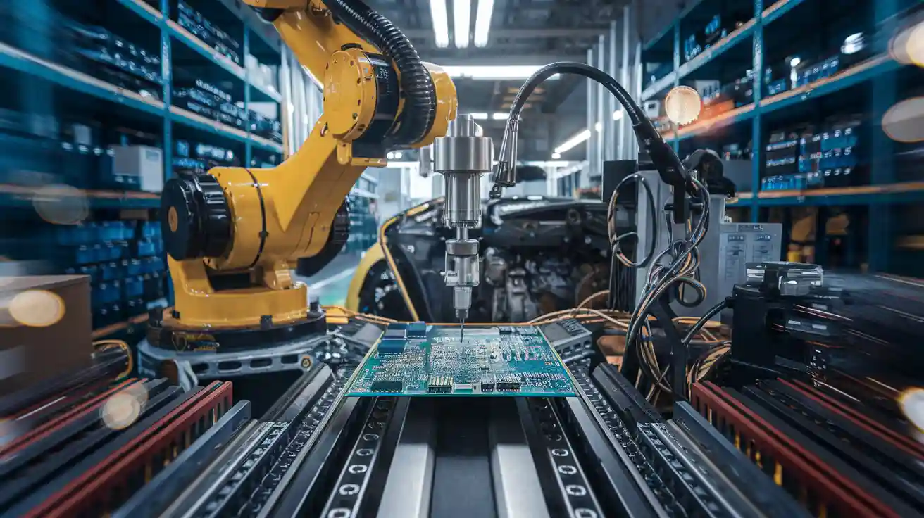
Step-by-Step Manufacturing Process
PCB Design and Prototyping
The manufacturing process begins with designing and prototyping the automotive PCB. You start by creating a schematic diagram that outlines the circuit’s functionality. Advanced software tools like Altium Designer or Eagle are used to translate this schematic into a detailed PCB layout. This layout defines the placement of components, routing of electrical connections, and layer stack-up.
Prototyping plays a crucial role in validating the design. During this stage, manufacturers produce a small batch of PCBs to test their functionality and reliability. Critical tests, such as board bring-up and functional testing, ensure the design meets quality standards before moving to mass production. Quick prototyping accelerates innovation, allowing you to bring new technologies to market faster.
Material Selection
Choosing the right materials is essential for ensuring the durability and performance of automotive PCBs. You need materials that can withstand harsh automotive conditions, including extreme temperatures, vibrations, and humidity. Commonly used materials include FR-4 for standard applications and polyimide for high-temperature environments.
Manufacturers also consider the thermal and electrical properties of materials. High-frequency laminates are often selected for advanced systems like radar and communication modules. Compliance with ISO9001 and ISO/TS16949 standards ensures that the materials meet industry requirements for quality and reliability.
Layering and Lamination
Layering and lamination involve stacking multiple layers of conductive and insulating materials to form the PCB. You begin by aligning the layers precisely to ensure accurate circuit formation. The layers are then bonded together using heat and pressure in a lamination press.
This process creates a robust structure capable of supporting complex circuitry. Multilayer PCBs enhance functionality in compact spaces, making them ideal for modern automotive systems. Thermal cycling tests (TCT) are conducted during this stage to assess the PCB’s performance under temperature variations, ensuring reliability in real-world conditions.
Etching and Circuit Formation
Etching is a critical step in creating the circuit patterns on your automotive PCB. During this process, manufacturers remove excess copper from the board, leaving behind the desired circuit traces. This step ensures that only the necessary conductive pathways remain, forming the electrical connections required for your PCB’s functionality.
The process begins with applying a protective layer, often a photoresist, over the copper surface. This layer shields specific areas of the copper while exposing others. Manufacturers then use a chemical solution, such as ferric chloride or ammonium persulfate, to dissolve the exposed copper. The result is a precise circuit pattern that matches your PCB design.
Tip: Proper etching ensures minimal signal interference and optimal electrical performance. Always verify the accuracy of the circuit pattern during this stage.
Advanced techniques, like laser etching, are sometimes used for high-density interconnect (HDI) PCBs. These methods provide greater precision, allowing you to achieve intricate designs for modern automotive systems.
Drilling and Plating
Drilling creates the holes needed for electrical connections between the PCB layers. These holes, known as vias, play a vital role in linking the different layers of your board. Manufacturers use computer-controlled drilling machines to achieve high accuracy, ensuring that the holes align perfectly with the circuit design.
After drilling, the plating process begins. This step involves depositing a thin layer of conductive material, typically copper, onto the walls of the drilled holes. This plating forms the electrical pathways that connect the layers. The process often includes electroplating, where an electric current helps deposit the copper evenly.
| Step | Purpose |
|---|---|
| Drilling | Creates vias for inter-layer connections. |
| Copper Plating | Establishes conductive pathways. |
High-quality drilling and plating are essential for the reliability of your automotive PCB. Poorly executed vias can lead to electrical failures, compromising the performance of critical systems.
Solder Mask Application
The solder mask is a protective layer applied to the PCB’s surface. It prevents solder from bridging between conductive traces during assembly, reducing the risk of short circuits. You’ll recognize this layer by its distinctive green color, though other colors like red or blue are also used.
Manufacturers apply the solder mask using a screen-printing process or an automated spray system. The mask covers the entire board except for the pads and vias, which remain exposed for soldering. After application, the board undergoes curing under ultraviolet (UV) light to harden the solder mask.
Note: The solder mask not only protects against solder bridging but also shields the PCB from environmental factors like moisture and dust.
This step enhances the durability and reliability of your automotive PCB, ensuring it performs well in harsh conditions. A properly applied solder mask also improves the board’s aesthetic appeal, giving it a clean and professional finish.
Silkscreen Printing
Silkscreen printing adds critical information to your automotive PCB. This step involves printing labels, symbols, and component identifiers on the board’s surface. These markings help you identify components, test points, and other essential details during assembly and maintenance.
Manufacturers use a fine mesh screen to apply the silkscreen layer. The process involves spreading ink over the screen, which transfers the design onto the PCB. Advanced techniques, such as UV-curable inks, ensure high precision and durability.
Tip: Clear and accurate silkscreen markings simplify troubleshooting and reduce assembly errors. Always verify the legibility of the printed details.
Silkscreen printing enhances the usability of your PCB. It ensures that technicians can quickly identify components, saving time during repairs or upgrades. While white ink is the most common choice, you may also encounter other colors like yellow or black, depending on the board’s design.
Surface Finishing
Surface finishing protects the exposed copper areas of your PCB and improves solderability. This step ensures that your board remains functional and corrosion-free over time. Common surface finishes include:
- HASL (Hot Air Solder Leveling): Provides a durable, solderable surface.
- ENIG (Electroless Nickel Immersion Gold): Offers excellent flatness and oxidation resistance.
- OSP (Organic Solderability Preservative): A cost-effective option for short-term protection.
Each finish has unique advantages. For example, ENIG is ideal for high-reliability applications, while HASL is more economical. You should choose a finish based on your PCB’s specific requirements.
Note: Surface finishing not only enhances solderability but also extends the lifespan of your PCB by preventing oxidation.
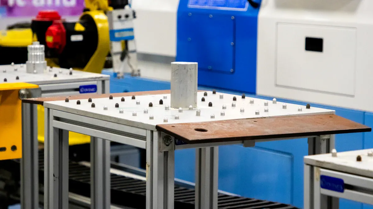
Quality Control and Testing
Quality control ensures that your automotive PCB meets industry standards and performs reliably. Manufacturers conduct rigorous testing to identify defects and verify functionality. Common tests include:
- Automated Optical Inspection (AOI): Detects surface defects like solder bridges or missing components.
- X-ray Inspection: Examines internal layers and solder joints for hidden flaws.
- Functional Testing: Simulates real-world conditions to ensure the PCB operates as intended.
These tests help you avoid costly failures in critical automotive systems. By prioritizing quality control, manufacturers deliver PCBs that meet the demanding standards of the automotive industry.

Reminder: Always choose a manufacturer with a robust quality control process to ensure the reliability of your automotive PCBs.
Assembly Process for Automotive PCBs
Solder Paste Application
The assembly process begins with applying solder paste to the PCB. This paste consists of tiny solder particles suspended in a flux medium, which helps create strong electrical connections. You’ll see this step performed using a stencil that aligns with the PCB layout. The stencil ensures the paste is applied only to the pads where components will be placed.
Precision is critical during this stage. Any misalignment or excess paste can lead to defects like solder bridging or insufficient connections. Manufacturers often use automated solder paste inspection systems to detect and correct these issues early. This ensures the reliability of the final product, especially in critical automotive applications.
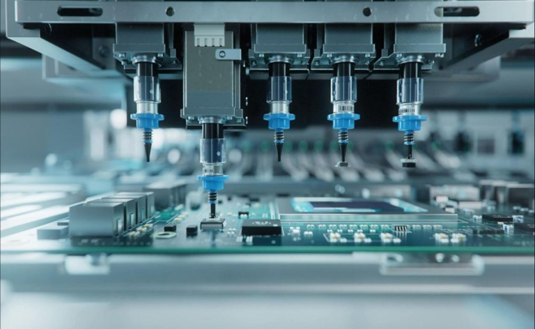
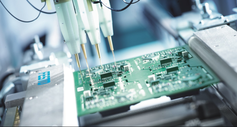
Component Placement
After applying the solder paste, the next step involves placing components onto the PCB. Automated pick-and-place machines handle this task with incredible speed and accuracy. These machines use vacuum nozzles to pick up components and position them precisely on the board.
You’ll notice that each component is placed according to the PCB design, ensuring proper functionality. High-resolution cameras and sensors guide the placement process, minimizing errors. Manufacturers also perform component inspections to verify that each part meets specifications and is free of damage. This step is vital for ensuring the performance and durability of the automotive PCB.
Reflow Soldering
Reflow soldering solidifies the connections between components and the PCB. During this process, the board passes through a reflow oven, where it is exposed to controlled heat. The solder paste melts, forming strong bonds between the components and the board.
The reflow oven operates in multiple zones, each with a specific temperature profile. This ensures the solder melts and cools uniformly, preventing defects like cold solder joints or overheating. Manufacturers often conduct Automated Optical Inspection (AOI) and X-ray inspection after reflow soldering. These methods detect issues such as misaligned components or hidden solder joint defects, ensuring the assembly meets quality standards.
Tip: AOI and X-ray inspections enhance the reliability of automotive PCBs by identifying defects that could compromise performance.
| Testing Method | Description |
|---|---|
| Environmental Stress Testing | Simulates real-world conditions such as thermal cycling, humidity exposure, and mechanical shocks. |
| Electrical Performance Testing | Verifies signal integrity, power distribution, and fault tolerance. |
| Safety Analysis | Conducts FMEA and fault tree analysis (FTA) to identify potential failure points and corrective measures. |
These rigorous testing methods ensure the assembled PCB can withstand the demanding conditions of automotive environments.
Inspection and Testing
Inspection and testing are critical steps in ensuring the reliability of automotive PCBs. You rely on these processes to identify defects and verify that the PCB meets performance standards before it reaches the final assembly stage.
Manufacturers use a combination of automated and manual inspection methods to achieve precision. Common techniques include:
- Automated Optical Inspection (AOI): This system uses high-resolution cameras to detect surface defects like solder bridges, missing components, or misalignments.
- X-ray Inspection: This method examines internal layers and solder joints, identifying hidden flaws that could compromise performance.
- In-Circuit Testing (ICT): ICT checks the electrical connections and verifies that each component functions as intended.
Tip: AOI and X-ray inspections are especially useful for detecting issues in high-density PCBs, where manual inspection may miss critical details.
Functional testing simulates real-world conditions to ensure the PCB operates reliably under stress. For example, environmental stress tests expose the PCB to extreme temperatures, vibrations, and humidity. These tests confirm that the board can withstand the harsh conditions of automotive environments.
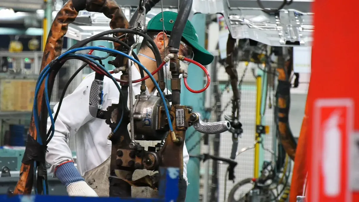
Final Assembly and Packaging
The final assembly process integrates the inspected PCBs into their respective automotive systems. You’ll see components like connectors, housings, and heat sinks added during this stage. Manufacturers use automated assembly lines to ensure precision and consistency.
Once assembled, the PCBs undergo a final round of testing. This step verifies that the entire system functions as expected. For example, a PCB used in an engine control unit will be tested for signal accuracy and response time.
After testing, the PCBs are packaged to protect them during transportation. Anti-static bags and shock-absorbing materials are commonly used to prevent damage. Proper labeling ensures that each package reaches its destination without confusion.
Reminder: Proper packaging not only protects the PCBs but also ensures compliance with industry standards for shipping and handling.
Key Considerations in Automotive PCB Production
Material Selection for Harsh Environments
When designing an automotive PCB, selecting the right materials is critical to ensure durability and performance in harsh conditions. You need materials that can withstand the extreme environments vehicles encounter daily. These include exposure to high temperatures, vibrations, and moisture.
Key material properties to consider include:
- Low moisture absorption to prevent degradation in humid conditions.
- High thermal conductivity for effective heat dissipation.
- Resistance to extreme temperature variations to maintain consistent performance.
- Mechanical strength to endure vibrations and shocks during vehicle operation.
- Compliance with environmental regulations like RoHS for safety and sustainability.
By prioritizing these characteristics, you ensure that your automotive PCB performs reliably, even in the most demanding scenarios.
Design for Manufacturing (DFM)
Design for Manufacturing (DFM) ensures that your PCB design is optimized for efficient production without compromising quality. You achieve this by simplifying the design to reduce manufacturing complexity and costs.
Key DFM principles include:
- Standardizing component sizes and placements to streamline assembly.
- Minimizing the number of layers to reduce production time and costs.
- Ensuring clearances and tolerances meet manufacturing capabilities.
By incorporating DFM early in the design process, you avoid costly revisions and ensure a smoother transition from prototype to mass production.