A good power supply PCBA begins with smart planning. A clear layout reduces noise and boosts efficiency. This helps circuits stay stable. Bad planning can cause overheating, signal problems, or device failure. Placing parts wisely and using better paths improves performance. Every choice in your layout affects how the power supply PCBA works. Plan carefully to build a strong and efficient power supply PCBA.
Key Takeaways
- Plan your PCB layout carefully to avoid noise and save energy. A good design keeps circuits stable and stops overheating.
- Use solid ground and power layers to work better. These layers lower resistance, improve signals, and manage heat well.
- Put decoupling capacitors near ICs to keep voltage steady. This also helps reduce noise and improves how circuits work.
- Make current paths short and straight to save power. This keeps voltage steady and parts cooler.
- Use good ways to handle heat. Add heat sinks and thermal vias to stop overheating and make your PCB last longer.
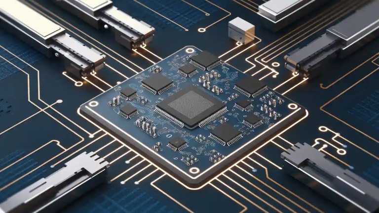
Understanding Power Supply PCBA Design
What Makes a Power Supply PCBA Effective?
A good power supply PCBA gives steady power with less noise. To do this, you need to focus on key things. Placing components correctly helps lower noise and keeps power stable. For example, putting decoupling capacitors near regulators keeps voltage steady.
Managing heat is also very important. Parts like regulators and transistors get hot and may stop working well. Heat sinks or thermal vias can help cool them down. Reducing electromagnetic interference (EMI) is also needed. Shielding and filters can keep signals clear.
| Metric/Characteristic | Description |
|---|---|
| Thermal Management | Cooling parts is important; heat comes from power and resistance. |
| EMI Reduction | Filters and shields help stop electromagnetic interference. |
| Component Placement | Placing parts well lowers noise and keeps power stable. |
| Power Integrity | Ground and power planes give low-resistance paths for power. |
| Decoupling and Bypass Capacitors | These capacitors reduce voltage dips and noise in the PCB. |
By focusing on these points, you can make a power supply PCBA that works well and lasts long.
The Importance of Layout in PCB Design
The PCB layout affects how well your power supply PCBA works. A smart layout lowers noise, handles heat better, and delivers power efficiently. For instance, a solid ground plane reduces resistance and keeps power stable. Short, wide traces cut down on power loss and stop voltage drops.
Simulation tools can help improve your layout. These tools show how circuits behave and help fix problems before making the PCB. For example:
- Signal simulations show issues like crosstalk or signal bouncing.
- Thermal simulations show heat spots, helping you avoid overheating.
- Power simulations show where current is high, ensuring smooth power flow.
Using these tools, you can make your layout better and safer.
Key Objectives of an Efficient Power Supply Layout
Making a good power supply layout means meeting some goals. First, grounding is important. A solid ground plane stops noise and gives a steady base for the circuit. Second, trace conductivity matters. Short, wide traces lose less power and work better.
- Grounding: Use a solid ground plane to stop noise problems.
- Trace Conductivity: Short, wide traces lose less power and work better.
- Component Placement: Place parts close to shorten trace lengths.
- Trace Routing: Keep signal traces away from power traces to avoid noise.
- Thermal Management: Use ways to cool down hot power supply parts.
By following these steps, you can make a power supply PCBA that works well and is reliable.
Challenges in Designing Effective PCB Layouts
Handling Electromagnetic Interference (EMI)
Electromagnetic interference can mess up your PCB’s signals. This causes noise and weakens performance. To fix EMI, use good routing and shielding methods. For example, placing power and ground planes close together helps. It reduces electric coupling and lowers unwanted currents. Computer tools like simulations can show EMI levels and problem spots.
Avoid long, unshielded traces. These can act like antennas and make EMI worse. Keep traces short and use paired wires for fast signals. Adding filters or ferrite beads can block extra noise. Solving EMI problems early makes your PCB work better and last longer.
Dealing with Heat Problems
Too much heat can harm your PCB parts. It can damage regulators and shorten the PCB’s life. Thermal tools can show where heat builds up. These tools check power use and air temperature to help you fix heat issues.
To cool your PCB, use heat sinks and thermal vias. Thermal vias move heat to cooler layers. Heat sinks pull heat away from hot parts. Spread out parts to let air flow better. Good heat control keeps your PCB cool and working well.
Keeping Signals Strong and Clear
Strong signals are key for a good PCB. Fast signals can weaken from noise, reflections, or crosstalk. To stop this, keep signal traces away from power traces. Avoid sharp turns in traces. Small loop areas also cut down on noise.
Place decoupling capacitors near regulators to steady voltage. These also lower noise. Tests show that noise-reducing tricks improve signal quality a lot. By focusing on signal strength, your PCB will work well in different situations.
Handling High Current Paths Effectively
Managing high current paths is key for a strong PCB design. High currents can cause heat, voltage drops, or damage parts. Using smart methods helps your PCB work well under tough conditions.
Pick parts that can handle high currents and heat safely. For example, regulators with good heat resistance last longer and stay cooler.
Use wider traces or thicker copper to lower heat and resistance. Thicker copper helps current flow better and reduces power loss. For very high currents, use power planes instead of regular traces. Power planes spread current evenly and manage heat better.
Thermal vias are also helpful. These small holes move heat to cooler layers of the PCB. This stops hotspots and keeps the board cool. Adding copper pours with thermal vias improves heat control even more.
Grounding is very important too. A solid ground plane keeps the PCB safe and stable. It also reduces noise and protects sensitive parts from damage.
Plan where to place parts and design the layout carefully. These steps will help you handle high currents well. Your PCB will be efficient, reliable, and meet performance needs.
Key Components and Placement in Power Supply PCBA
Capacitors and Their Role
Capacitors are important for keeping your power supply stable. Where you place them affects how well your PCB works. Knowing their job helps you design a layout that reduces noise and keeps voltage steady.
Decoupling Capacitors for Noise Reduction
Decoupling capacitors help cut down noise in your PCB. They keep voltage steady by blocking high-frequency noise and sending it to the ground. Put these capacitors very close to the ICs to stop voltage problems. Ceramic capacitors work best for high-frequency noise because they have low inductance. For low-frequency noise, use electrolytic capacitors instead.
Place power supply parts close together to shorten trace lengths. Keep signal traces away from power supplies to avoid noise issues.
Bulk Capacitors for Voltage Stabilization
Bulk capacitors act like energy storage to keep voltage steady. They handle sudden changes in current to give smooth power to parts. Place them near voltage regulators to lower voltage spikes and ripples. This setup improves efficiency and reduces resistance.
- Decoupling capacitors block high-frequency noise and steady power.
- Bulk capacitors handle low-frequency noise and voltage changes.
- Good placement lowers resistance and boosts performance.
Inductors and Their Placement
Inductors control current flow and reduce electromagnetic interference (EMI). Place them near the ICs they support, but avoid large copper areas to stop EMI. Keep sensitive traces away from inductors to avoid energy losses. Placing inductors well saves space and improves signal quality and heat control.
- Put inductors close to ICs for better results.
- Don’t place sensitive traces under inductors to avoid problems.
- Use smart routing to manage heat and EMI better.
Feedback Traces for Stability
Feedback traces help keep your power supply stable by controlling voltage. Keep these traces short and direct to avoid noise and delays. Don’t route them near noisy parts or high-current paths. Placing feedback traces correctly makes your PCB more reliable and efficient.
By placing parts carefully, you can make a power supply PCB that works well and lasts long.
Power and Ground Planes for Better PCB Performance
Power and ground planes are key for a strong PCB design. These large metal layers help current flow smoothly and reduce noise. A good ground plane keeps your PCB working well in different situations.
Power planes spread voltage evenly, while ground planes support signals. Together, they lower resistance and improve circuit performance. For example, placing a solid ground plane under high-current paths stops voltage drops. This also keeps regulators steady for reliable power.
Using these planes makes trace routing easier. Instead of winding traces around parts, you can use the planes to connect them. This keeps the layout simple and easy to build. The large surface area also spreads heat, avoiding hotspots and helping your PCB last longer.
Tip: Place power and ground planes close to each other. This reduces electromagnetic interference (EMI) and improves signal quality.
Power and ground planes do more than cut noise. They also help with voltage recovery, EMI shielding, and heat control. The table below shows their main benefits:
| Benefit | Description |
|---|---|
| Voltage Recovery | Gives low-resistance paths for current, keeping voltage steady. |
| Signal Integrity | Provides a stable base for signals, reducing noise and interference. |
| Reduction of Noise | Large metal areas lower noise that can harm circuits. |
| EMI Shielding | Blocks unwanted signals, improving electromagnetic compatibility. |
| Heat Dissipation | Spreads heat from parts, stopping hotspots and improving reliability. |
| Reduced Impedance | Lowers resistance and boosts circuit performance. |
| Ease of Routing | Makes connecting parts simpler, improving manufacturability. |
| Power Supply Integrity | Reduces power spikes, ensuring smooth power delivery. |
By adding power and ground planes to your PCB, you improve its performance and durability. This design choice supports regulators and keeps your circuit stable and efficient.
Best Practices for Effective PCB Layouts
Make Current Paths Short and Direct
Short and wide paths help power flow better in PCBs. They lower resistance and stop power loss. This keeps regulators cool and working well. Avoid long or winding paths for high-current traces. These can cause voltage drops and waste energy.
Use simulations to find areas with too much current. For example, power simulations show where voltage drops happen. Fixing these problems early makes your PCB work better overall.
| Benefit Type | Description |
|---|---|
| Power Integrity | Delivers power smoothly and avoids voltage drops. |
| Signal Integrity | Keeps signals strong by reducing problems in transmission. |
| PCB Layout Optimization | Spots issues like long traces or mismatched impedance. |
Tip: Use thicker copper for high-current paths. This improves power flow and reduces heat.
Use Ground Planes for Better Stability
A solid ground plane helps your PCB stay stable. It gives a low-resistance path for current and cuts down noise. Placing it near the power plane blocks interference and keeps signals clear.
Ground planes also make routing easier. They act as a shared base for all parts, simplifying the design. Plus, they spread heat away from hot parts like regulators, stopping damage.
| Optimization Technique | Importance |
|---|---|
| Signal Integrity | Keeps signals clean for better performance. |
| EMI/EMC | Reduces interference for reliable operation. |
| Thermal Management | Spreads heat to avoid part failures. |
Note: Don’t split the ground plane too much. This can cause noise and weaken stability.
Keep Loop Areas Small to Lower Noise
Big loop areas can act like antennas and cause noise. Keeping loops small helps reduce interference and boosts efficiency. Place decoupling capacitors close to regulators to shrink loop areas and steady voltage.
When routing, avoid sharp turns or long paths. Use short, direct routes to cut down on noise risks. Simulations can show problem spots and help improve your layout.
| Simulation Type | Purpose |
|---|---|
| Signal Integrity Simulations | Finds issues like signal reflections or crosstalk. |
| Power Distribution Simulations | Shows areas with high current or voltage drops. |
| Thermal Simulations | Predicts heat buildup to improve cooling. |
Tip: Place power and ground planes close together. This reduces loop areas and blocks noise better.
Implement Proper Thermal Management
Good heat control keeps your PCB working well and lasting longer. If parts like regulators get too hot, they might stop working or fail. You can avoid this by using smart ways to manage heat.
- Use thermal vias and copper thickness: Thermal vias move heat from hot parts to cooler PCB layers. Thicker copper spreads heat better, helping parts stay cool.
- Strategic component placement: Put hot parts, like regulators, away from sensitive ones. This stops heat from harming nearby circuits.
- Manage thermal resistance: Lower thermal resistance helps heat move easily to heat sinks or cooling tools.
- Maintain safe temperatures: Keeping parts within safe temperature limits makes them last longer.
Tip: Use thermal simulation tools to find hot spots and improve cooling.
By following these ideas, your PCB will handle heat well and stay reliable for a long time.
Maintain Adequate Spacing Between Components
Leaving enough space between parts is important for a good PCB design. Crowded layouts can cause signal problems, EMI, or even short circuits. Using proper spacing rules avoids these issues.
- Maintain signal integrity: Space between traces stops crosstalk and keeps signals clear.
- Minimize EMI: Spacing parts and traces correctly lowers electromagnetic interference for better performance.
- Follow manufacturer specifications: Trace width and clearance must match the maker’s rules to avoid production problems.
- Prevent short circuits: Enough space between traces and parts stops accidental shorts during use.
Note: Always check your PCB maker’s rules to ensure your design meets their spacing needs.
By keeping parts spaced well, your PCB will work better and be easier to build. This step is key for making a strong and efficient power supply.
Avoiding Critical Design Mistakes
Skipping EMI Shielding Methods
Not using EMI shielding can harm your PCB’s performance. EMI can mess up signals, lower efficiency, or even break devices. To stop this, use good shielding methods when designing.
| Shielding Method | What It Does |
|---|---|
| Enclosure Shielding | Use metal covers to trap EMI inside the PCB. This stops it from spreading to other parts or outside. |
| Trace Shielding | Place a ground plane above or below sensitive traces. This blocks noise and keeps signals clean. |
| Cable Shielding | Shield external cables and connect the shield to the PCB ground. This reduces outside interference. |
Using these methods lowers EMI and makes your PCB more reliable.
Tip: Keep power and ground planes close to cut EMI and improve signals.
Wrong Placement of Decoupling Capacitors
Putting decoupling capacitors in the wrong spot can hurt your PCB. These capacitors keep voltage steady and reduce noise. But they only work well if placed near the ICs they support. This reduces unwanted resistance and improves noise control.
| Aspect | Details |
|---|---|
| Study Focus | How aging and heat affect capacitor performance in PCBs. |
| Key Findings | Aging and heat can weaken capacitors, causing early system problems. |
| Implications | Add extra capacitors to keep performance steady over time. |
Bad placement can cause voltage issues and shorten your PCB’s life. Always place capacitors carefully for better reliability.
Forgetting Thermal Management
Ignoring heat control can overheat your PCB and damage parts. High-power parts like regulators create a lot of heat. Without cooling, your PCB might fail.
To handle heat well:
- Use thermal vias to move heat to cooler layers.
- Add heat sinks to pull heat away from hot parts.
- Make sure copper thickness fits your design’s heat needs.
Design Rule Check (DRC) tools can find heat problems early. They ensure your design meets rules and avoids costly errors. Managing heat early makes your PCB last longer and work better.
Creating Long or Complex Feedback Loops
Long feedback loops can hurt your PCB’s stability. They add delays and noise, making voltage regulation unstable. Short and simple feedback loops are better for reliable circuits.
Place feedback parts like resistors and capacitors close to the controller IC. This keeps traces short and reduces noise problems. Avoid placing feedback traces near noisy or high-current areas. These spots can cause interference and weaken signals.
Sharp turns or extra detours in loops are bad. They increase resistance and lower signal quality. Use straight paths to keep feedback signals clean. Simulation tools can find and fix bad feedback paths before building the PCB.
Tip: Put ground planes under feedback traces to block noise and improve signals.
Simplifying feedback loops makes your PCB more stable and efficient. This small change improves how your power supply works.
Overlooking Proper Grounding Techniques
Good grounding is key for a strong PCB design. Bad grounding can cause noise, voltage changes, or broken parts. A solid ground keeps your PCB working well and protects sensitive parts.
Follow these grounding tips:
- Use a ground plane to lower noise and keep voltage steady.
- Add vias to the ground plane to connect layers and stop ground loops.
- Ground connectors with multiple pins to avoid mismatched impedance.
Ground loops act like antennas and bring in noise. These loops can mess up signals and hurt your PCB’s performance. Keep the ground plane whole and avoid splitting it. Place vias carefully to keep current flowing smoothly.
Note: Use simulation tools to check your grounding design. These tools find problems and help improve your layout.
Good grounding makes your PCB strong and reliable. It helps your power supply work well in different situations and last longer.
Making a good PCB power supply layout is very important. It helps circuits work well and last longer. A smart layout lowers noise, gives steady power, and protects parts. Focus on things like grounding, trace paths, and cooling to make your design better.
Here’s a quick guide to follow:
- Keep current paths short for better power flow.
- Use solid ground planes to cut noise and stay stable.
- Place decoupling capacitors near parts to block noise.
- Manage heat properly to stop parts from overheating.
Avoid mistakes like skipping EMI shielding, placing capacitors wrong, or ignoring heat issues. Experts agree that following these steps keeps signals clear, parts cool, and designs easy to build.
“A good PCB layout is key for a strong power supply. Using these tips makes circuits work well in all conditions.”
Start now. Use these ideas in your next project to see better results and longer-lasting designs.
FAQ
1. Why is grounding important in PCB power supply layouts?
Grounding keeps your PCB stable and reduces noise. A solid ground plane stops interference and keeps voltage steady. Without good grounding, your circuit might not work well or could fail. Always focus on grounding to make your PCB reliable.
Tip: Use a full ground plane to avoid loops and noise.
2. How can I lower electromagnetic interference (EMI) in my design?
Keep traces short and use paired wires for signals. Place power and ground planes close together. Filters or ferrite beads can block extra noise. These steps help your PCB work smoothly.
Note: Simulations can find EMI trouble spots before building.
3. What’s the best way to handle heat in a power supply PCB?
Use thermal vias, heat sinks, and thicker copper to spread heat. Space out parts to let air flow better. Good heat control stops overheating and helps your PCB last longer.
Tip: Keep hot parts away from sensitive ones to avoid damage.
4. Where should decoupling capacitors go for best results?
Put decoupling capacitors very close to the ICs they support. This lowers noise and keeps voltage steady. Proper placement makes your circuit work well in different conditions.
Reminder: Use ceramic capacitors for high-frequency noise and electrolytic ones for low-frequency noise.
5. How do I make high-current paths more efficient?
Use wider traces or thicker copper to lower resistance and heat. Power planes are even better for spreading current evenly. These methods improve performance and protect parts.
Pro Tip: Simulate your design to find and fix high-current issues.