Choosing the right PCB boards is critical to the success of your project. A well-suited PCB board ensures optimal performance, enhances durability, and keeps costs under control. Material properties, such as dielectric constant and thermal conductivity, directly influence cost-efficiency. For instance, standard materials like FR-4 are more affordable due to their compatibility with standard manufacturing processes, while specialized materials may require costly techniques. Balancing cost and performance is essential to avoid overspending while meeting application needs. Mistakes like placing parts too close to the PCB board’s edge or using unnecessary layers can compromise functionality and increase expenses. Thoughtful PCB board design and manufacturing decisions can save you time and resources.
Key Takeaways
- Picking the right PCB—rigid, flexible, or rigid-flex—depends on your project’s need for strength, bending, or space-saving.
- Choosing materials is important; FR-4 is cheap, but special materials work better for tough tasks.
- Testing your PCB design early finds mistakes, saves money, and makes sure it works well.
- Think about heat and water when picking materials to make your PCB last longer and work better.
- Check PCB makers for good reviews, skills, and certifications to get great boards.
Understanding PCB Types
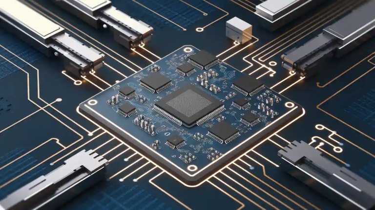
Printed circuit boards (PCBs) come in various types, each designed to meet specific application needs. Understanding these types helps you select the most suitable option for your project. Below, we explore three common PCB types: rigid, flexible, and rigid-flex.
Rigid PCBs
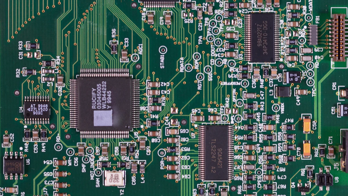
Rigid PCBs are the most widely used type in modern electronics. These boards are made from solid, inflexible materials like FR4, which provides excellent strength and insulation. You’ll find rigid PCBs in consumer appliances such as washing machines, mobile phones, and microwave ovens. They are also essential in industries like telecommunications, aerospace, and automotive.
| Industry | Application |
|---|---|
| Consumer Appliances | Mobile phones, TV remotes, washing machines, and multimedia players. |
| Automotive | Navigation systems, LCDs, and electronic control modules. |
| Aerospace | Radar equipment, avionics systems, and motion sensors. |
Rigid PCBs are ideal for applications requiring durability and reliability. However, their lack of flexibility limits their use in compact or dynamic designs.
Flexible PCBs
Flexible PCBs are made from bendable materials like polyimide, allowing them to fit into tight spaces. These boards are lighter and more space-efficient than rigid PCBs, making them perfect for modern electronics prioritizing compactness.
| Advantage | Description |
|---|---|
| Flexibility | Can be folded or bent to fit various applications. |
| Reduced Weight | Lighter, essential for portable devices. |
| Space Efficiency | Eliminates connectors, saving space in compact designs. |
Flexible PCBs are commonly used in wearable electronics, medical devices, and automotive systems. Despite their advantages, they present challenges like complex design rules and higher manufacturing costs.
Rigid-Flex PCBs
Rigid-flex PCBs combine the strengths of rigid and flexible boards. They feature rigid sections for mounting components and flexible sections for connectivity. This hybrid design makes them suitable for compact devices requiring both durability and flexibility.
| Industry | Application |
|---|---|
| Medical | Pacemakers, imaging equipment, and handheld monitoring units. |
| Military | Communication systems and weapons guidance systems. |
| Consumer Appliances | Wearable electronics and mobile phones. |
Rigid-flex PCBs reduce the need for connectors, improving reliability and saving space. They are widely used in industries like aerospace, telecommunications, and medical technology.
By understanding these PCB types, you can make informed decisions that align with your project’s requirements.
High-Density Interconnect (HDI) PCBs
High-Density Interconnect (HDI) PCBs are a game-changer for high-performance applications. These boards excel in scenarios where space, weight, and reliability are critical. You’ll find HDI PCBs in advanced electronics like smartphones, medical devices, and aerospace systems. Their compact design uses blind vias, buried vias, and microvias to maximize board space while maintaining functionality. This makes them ideal for projects requiring miniaturization without compromising performance.
HDI PCBs offer several advantages:
- Phenomenal versatility: They adapt to demanding environments and applications.
- Compact design: Their advanced via technology minimizes board size.
- Better signal integrity: Shorter signal paths improve quality and reduce interference.
- High reliability: Stacked vias enhance durability under extreme conditions.
- Cost-effective: They reduce the number of layers needed, saving costs in the long run.
While HDI PCBs may have higher initial costs due to complex designs and additional laminations, they often lead to cost savings during production. Improved manufacturing yields and reduced material waste contribute to their overall efficiency. By choosing HDI PCBs, you can achieve a balance between performance and cost-effectiveness.
Specialized PCBs
Metal Core PCBs
Metal Core PCBs are designed for applications requiring superior heat dissipation. These boards use a metal core, typically aluminum or copper, to transfer heat away from components. You’ll often see them in LED lighting, power supplies, and automotive systems. The metal core enhances thermal conductivity, ensuring your PCB operates reliably under high temperatures. This makes them a top choice for projects where heat management is critical.
RF and Microwave PCBs
RF and Microwave PCBs cater to high-frequency applications. These boards use specialized materials like PTFE to handle frequencies above 1 GHz. You’ll find them in communication systems, radar equipment, and satellite technology. Their design minimizes signal loss and interference, ensuring optimal performance. If your project involves high-speed data transmission, RF and Microwave PCBs provide the precision and reliability you need.
Key Factors in PCB Component Selection
Selecting the right components for your PCB is crucial to achieving optimal performance and durability. By focusing on materials, compatibility, and environmental conditions, you can ensure your PCB meets the performance specifications of your project.
Choosing the Right Materials
Choosing the right materials is one of the most critical steps in PCB component selection. The materials you choose directly impact the board’s electrical, thermal, and mechanical properties. Consider the following factors:
- Electrical performance, including dielectric constant and signal integrity.
- Thermal performance, such as heat dissipation and thermal conductivity.
- Mechanical properties, including strength and flexibility.
- Environmental conditions like moisture resistance and temperature tolerance.
- Cost and manufacturing constraints.
FR4 and its Variants
FR4 is the most common material for PCB boards due to its affordability and versatility. It offers moderate thermal conductivity and mechanical strength, making it suitable for standard electronics. However, for high-performance applications, you may need to explore FR4 variants with enhanced properties.
| Property | FR4 | High-Temperature Materials (Polyimide/Ceramic) |
|---|---|---|
| Glass Transition Temperature (Tg) | 130°C to 180°C | 280°C to 350°C (Polyimide) |
| Thermal Conductivity | ~0.3 W/m·K | ~24 W/m·K (Alumina), ~170 W/m·K (AlN) |
| Mechanical Strength | Moderate | High (Polyimide) |
| Cost | Lower | Higher (Polyimide) |
| Applications | Standard electronics | Aerospace, automotive, industrial electronics |
High-Temperature Materials
High-temperature materials like polyimide or ceramic are ideal for applications requiring superior thermal performance. These materials withstand extreme temperatures, making them suitable for aerospace and automotive industries. While they offer excellent value in demanding environments, their higher cost may not justify their use in standard applications.
Metal Core Materials
Metal core materials, such as aluminum or copper, provide exceptional heat dissipation. These materials are essential for applications like LED lighting and power supplies, where thermal management is critical. By using metal core materials, you can enhance the overall value of your PCB.
Electrical and Physical Compatibility
Ensuring electrical and physical compatibility is vital for reliable PCB performance.
Current and Voltage Requirements
Your PCB must handle the required current and voltage without failure. Ensure the power supply delivers consistent voltage and current to all components. Overlooking maximum and minimum ratings can lead to component failure or reduced performance.
Board Size and Thickness
The size and thickness of your PCB influence its mechanical strength and compatibility with enclosures. Choose dimensions that align with your project’s design while maintaining structural integrity.
Environmental Conditions
Environmental factors significantly affect the longevity and reliability of PCB boards.
Operating Temperature
Temperature variations can cause mechanical stress, leading to solder joint failures. High temperatures may also shorten the lifespan of components. Select materials and designs that withstand your application’s temperature range.
Moisture and Chemical Resistance
Moisture can corrode PCB materials, causing short circuits and performance degradation. Long-term exposure to humidity may also slow circuit speeds in high-frequency applications. Opt for materials with moisture and chemical resistance to ensure durability in harsh environments.
Tip: Consider the environmental challenges your PCB may face, such as vibration, EMI interference, or extreme temperatures. Addressing these factors during the design phase can save you from costly failures later.
Cost and Budget Considerations
Cost plays a pivotal role in selecting the right PCB for your project. Balancing performance and affordability ensures you achieve your goals without exceeding your budget. Understanding how material and design choices influence cost can help you make informed decisions.
The cost of PCB materials varies widely based on their type and properties. Standard materials like FR-4 are affordable and versatile, making them a popular choice for many applications. However, specialized materials, such as polyimide or metal cores, often come with higher price tags. These materials may be necessary for high-frequency or high-temperature environments, but they can significantly increase your project’s expenses. Evaluating the trade-offs between cost and performance is essential to avoid overspending while meeting your project’s requirements.
Design complexity also impacts cost. Adding extra layers, using advanced via technologies, or incorporating intricate layouts can drive up manufacturing expenses. For instance, HDI PCBs, while compact and high-performing, often require additional laminations and specialized processes, increasing production costs. Simplifying your design where possible can help you stay within budget without compromising functionality.
You should also consider production volume when planning your budget. Prototyping and small-batch production typically cost more per unit than large-scale manufacturing. If your project involves mass production, you can negotiate lower costs with manufacturers. On the other hand, for smaller projects, optimizing your design to minimize material waste and assembly time can reduce expenses.
Tip: Always communicate your budget constraints to your PCB manufacturer. They can suggest cost-effective materials and design adjustments to help you achieve your goals without unnecessary expenses.
By carefully analyzing cost and budget considerations, you can select PCB boards that align with your financial and technical requirements.
Design Considerations for PCB Boards
Layout and Routing
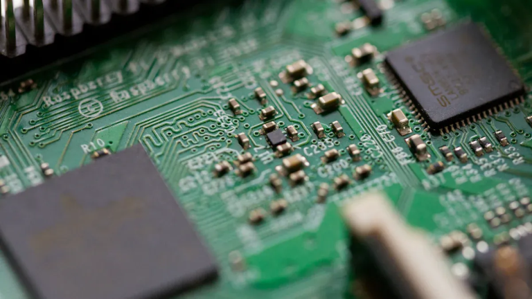
Component Placement
Effective component placement is the foundation of a successful pcb layout design. You should position components logically to minimize trace lengths and reduce signal interference. Group related components, such as resistors and capacitors, near their corresponding ICs to enhance performance. Avoid placing components too close to the edges of the pcb boards, as this can lead to mechanical stress and potential damage during assembly. Proper placement ensures a clean layout and simplifies the routing process.
Trace Width and Spacing
Trace width and spacing play a critical role in maintaining signal integrity and preventing short circuits. Wider traces handle higher currents, while narrower traces are suitable for low-power signals. Maintain consistent spacing between traces to avoid crosstalk and electromagnetic interference (EMI). For high-frequency designs, use impedance-controlled traces to ensure reliable signal transmission. Avoid sharp angles in traces, as they can cause signal reflection and degrade performance.
Tip: Keep traces as short as possible and limit the use of vias to improve reliability and reduce manufacturing costs.
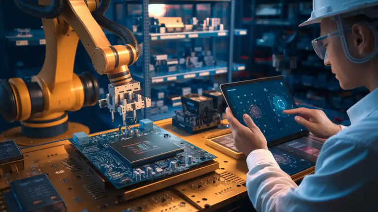
Manufacturability
Design for Manufacturing (DFM) Guidelines
Design for Manufacturing (DFM) ensures your pcb is easy to produce without compromising quality. Simplify the circuit board design by minimizing the number of layers and components. Use standard materials and dimensions to reduce production costs. Incorporate features that facilitate assembly, such as fiducial markers and clear labeling. Following DFM principles improves manufacturability and reduces the risk of errors during production.
Panelization and Assembly
Panelization enhances efficiency by allowing multiple pcb boards to be manufactured on a single panel. This approach reduces production time and costs while improving yield. It also protects boards from shocks and vibrations during assembly. For surface-mount technology (SMT) components, panelization simplifies the assembly process and ensures consistent quality. By optimizing panelization, you can streamline the pcb prototype assembly process and achieve better results.
Testing and Prototyping
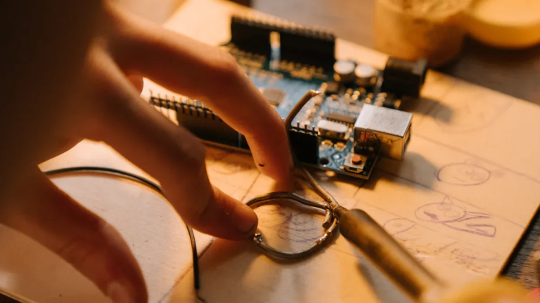
Importance of Prototyping
Prototyping is an essential step in the pcb design process. It allows you to test and refine your design before full-scale production. By identifying errors early, you can minimize imperfections and reduce project costs. Prototyping ensures the functionality of individual components and provides a competitive edge by accelerating market entry. A well-executed pcb prototype assembly saves time and resources while ensuring reliability.
Testing for Performance and Reliability
Testing verifies that your pcb meets performance and reliability standards. Conduct functional tests to ensure all components operate as intended. Use environmental tests to evaluate the board’s resistance to temperature, moisture, and vibration. By addressing potential issues during the testing phase, you can avoid costly failures in the final product. Testing is a critical part of design and engineering services, ensuring your pcb performs optimally in real-world conditions.
Note: Always prioritize thorough testing during the prototype phase to ensure a robust and reliable final product.
Tips for Choosing a PCB Manufacturer
Selecting the right PCB assembly partner is crucial for ensuring defect-free PCBs and achieving project success. By focusing on quality standards, manufacturing capabilities, and customer support, you can make an informed decision when choosing a PCB manufacturer.
Quality Standards and Certifications
Certifications reflect a manufacturer’s commitment to high-quality standards and reliability. When evaluating a PCB assembly partner, prioritize those with recognized certifications.
- ISO Certifications: ISO 9001 ensures consistent quality management practices, while ISO 13485 and AS9100 cater to medical and aerospace industries.
- IPC Certifications: IPC-A-610 guarantees adherence to assembly standards, with Class 1 for consumer electronics, Class 2 for industrial applications, and Class 3 for aerospace and military.
- RoHS Compliance: This certification ensures the reduction of hazardous substances in PCB manufacturing.
- UL Certifications: UL-listed manufacturers meet stringent safety requirements, ensuring defect-free PCBs.
These certifications demonstrate a manufacturer’s ability to deliver high-quality PCBs that meet industry standards.
Manufacturing Capabilities
A manufacturer’s capabilities determine whether they can meet your project’s technical requirements. When choosing a PCB manufacturer, assess their expertise in handling complex designs.
- Minimum and Maximum Layer Count: Ensure the manufacturer can produce PCBs with the required number of layers, whether single-layer or multi-layered designs.
- Advanced Features: Manufacturers with HDI technology excel in producing high-density interconnect PCBs. Similarly, expertise in flexible and rigid-flex PCBs is essential for compact and dynamic designs.
Evaluate their testing procedures and quality control processes to ensure reliability before shipment. A capable manufacturer can handle diverse requirements, from high-frequency PCBs to intricate layouts.
Customer Support and Communication
Effective communication and support play a vital role in the success of your PCB project. When choosing a PCB manufacturer, consider their responsiveness and resources.
- Responsiveness and Technical Support: Prompt responses to queries and technical assistance minimize delays and align project objectives.
- Online Tools and Resources: Many manufacturers offer user-friendly platforms where you can upload designs, receive instant quotes, and track production status. These tools simplify the process and reduce errors.
Transparent communication fosters collaboration and ensures high-quality standards are met throughout the project lifecycle.
Tip: Ask questions to evaluate a PCB manufacturer’s certifications, capabilities, and support. This approach helps you identify the best PCB assembly partner for your needs.
Reviews and Reputation
When choosing a PCB manufacturer, understanding their reputation and reviews is essential. A strong reputation reflects the manufacturer’s ability to deliver high-quality and reliable PCB boards consistently. By evaluating customer testimonials and industry experience, you can make an informed decision.
Customer Testimonials
Customer testimonials provide valuable insights into a manufacturer’s quality and reliability. They highlight real-world experiences, helping you assess whether the manufacturer meets its promises. Positive reviews often indicate consistent performance and customer satisfaction. On the other hand, negative feedback can reveal potential issues, such as delays or quality concerns.
| Evidence | Description |
|---|---|
| Customer Testimonials | They offer insights into the manufacturer’s reliability and product quality based on past customer experiences. |
| Manufacturer’s Reputation | A strong reputation indicates the ability to consistently deliver high-quality PCBs, supported by positive customer reviews. |
When reviewing testimonials, focus on recurring themes. For example, consistent praise for timely delivery and defect-free products suggests a reliable partner. Testimonials also help you gauge how well the manufacturer handles challenges, such as custom designs or tight deadlines. By analyzing these reviews, you can better understand the manufacturer’s strengths and weaknesses.
Industry Experience
A manufacturer’s industry experience plays a critical role in ensuring quality and reliability. Experienced manufacturers have a proven track record of handling diverse projects and meeting industry standards. Their expertise often translates into better design support, advanced capabilities, and fewer production errors.
Consider the following factors when evaluating a manufacturer’s experience:
- Assess their reputation in the industry.
- Look for a proven track record supported by positive customer reviews.
- Check customer testimonials, case studies, and industry ratings.
- Ensure they have experience with your specific PCB requirements, such as HDI or flexible designs.
A manufacturer with extensive experience often delivers superior results. Their familiarity with industry challenges enables them to provide innovative solutions and maintain high standards. By prioritizing reputation and reviews, you can select a manufacturer that aligns with your project’s needs.
Tip: Always verify a manufacturer’s experience and reputation before committing to a partnership. This step ensures you receive high-quality PCB boards that meet your expectations.
Selecting the right pcb for your project begins with understanding the types and materials available. Each material impacts performance, durability, and heat management, allowing you to make informed decisions for optimal results. Design considerations, such as grounding techniques and component placement, ensure compatibility and functionality. A reliable manufacturer enhances quality and simplifies production. Align your pcb boards with project requirements, and always verify the Bill of Materials for efficient assembly. By following these steps, you can achieve a durable, high-performing pcb that meets your goals.
FAQ
What is the most common material used for PCB boards?
FR4 is the most common material due to its affordability and versatility. It offers moderate thermal conductivity and mechanical strength, making it suitable for standard electronics. For high-performance applications, you can explore FR4 variants with enhanced properties.
How do you choose the right PCB type for your project?
Consider your project’s requirements, such as flexibility, durability, and space constraints. For compact designs, flexible PCBs work best. For high-performance needs, HDI PCBs are ideal. Evaluate your application’s environment and performance goals before deciding.
Why is prototyping important in PCB design?
Prototyping helps you test and refine your design before full-scale production. It identifies errors early, saving time and costs. A prototype ensures functionality and reliability, giving you confidence in the final product’s performance.
What factors affect PCB manufacturing costs?
Material choice, design complexity, and production volume impact costs. Specialized materials like polyimide or metal cores increase expenses. Adding extra layers or advanced features, such as HDI technology, also raises costs. Simplifying your design can help reduce expenses.
How do you ensure a PCB performs well in harsh environments?
Select materials with high-temperature tolerance and moisture resistance. Use protective coatings to shield against chemicals and humidity. Design the PCB to withstand vibrations and EMI interference. Testing under simulated conditions ensures reliability in real-world applications.
Tip: Always communicate your project’s environmental challenges to your manufacturer for tailored solutions.